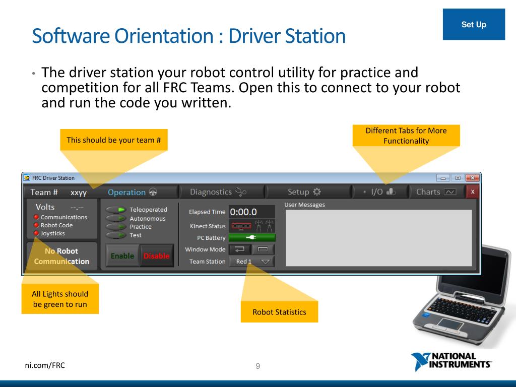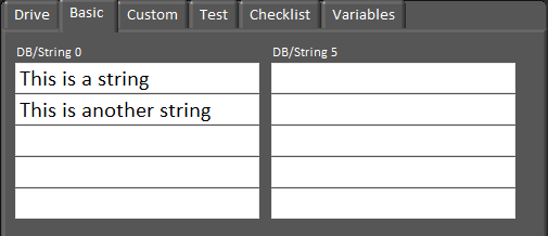

- HOW TO SETUP FRC DRIVER STATION INSTALL
- HOW TO SETUP FRC DRIVER STATION CODE
- HOW TO SETUP FRC DRIVER STATION DOWNLOAD
The right of the while Loop - this VI will unreserve the port. Get a Close.vi from the LINX palette and place it to Wire the error out from the Open to the While Loop. Wire the top right terminal (LINX Resource) to the While Loop and set it to a Shift Register Select the port the Arduino is connected to. Right click on the top left terminal of the Open.vi and select Create -> Constant Place it to the left of the new While Loop This VI creates the communication link to the Arduino for us.

Open the palette (right click if it is not already open) and select MakerHub -> LINX -> Open Scroll to the top (the region that is expected to be edited), and add a While Loop. Go to the block diagram (press CTRL + e or select Window -> Show Block Diagram).
HOW TO SETUP FRC DRIVER STATION CODE
This is a source code version of the default dashboard. In the Project Explorer window, select and open “Dashboard Main.vi” In the configuration dialogue choose what you would like to name the project and where to save it and click next.
HOW TO SETUP FRC DRIVER STATION DOWNLOAD
Once the download finishes, press “Finish” to return to the LabVIEW welcome screen. This firmware implements a communication interface that allows for the VIs we installed earlier to control the I/O on the Arduino.Ĭlick next to download the default firmware image Select the port that the Arduino is connected to (See Arduino getting started info for help) and click next to download firmware. Select the correct type of Arduino firmware to use and click next.
HOW TO SETUP FRC DRIVER STATION INSTALL
You can download and install it with the default IDE atįrom the launch screen (or any screen actually) select Tools -> MakerHub -> LINX -> (Note: The Arduino driver is needed for this step. To see where the installed library is in the palette, select ‘Show in Palettes’Ĭonnect the Arduino to the computer and open LabVIEW If prompted, select to open in Package Manager. The library we will use to interact with the Arduino from LabVIEW is called the LabVIEW Interface for Arduino (now, LINX) which we need to download and install to LabVIEW. We wire 5V and Ground from the Arduino to the two outer pins of the potentiometer and connect the wiper pin to A0. Setupįirst, we wire a potentiometer so that it can act as an Analog Input to the Arduino. The setup presented below can be used to read or write to/from any of the pins on the Arduino (including writing PWM out). The TI Launchpad allows for the input to the driverstation by acting as an extra Joystick but requires a bit of setup and is only an input.īelow is presented a setup that allows for an Arduino to be used for generic I/O on the Driver Station through the LabVIEW Interface for Arduino (now, LINX).įor this tutorial, we will implement reading a potentiometer and displaying it on the Dashboard. Sometimes it was an abort button, other times a potentiometer to select an auto program, and still others we wanted to put LED’s on the Driver Station that would light up to alert the drivers/coach to something (game piece acquired, aligned for shot, etc.) Many of the years that the authors have been involved with FRC, we wanted to collect I/O on the Driver Station. FRC LabVIEW Tutorials - Arduino - Dashboard Background


 0 kommentar(er)
